|
|
|
|
|
|
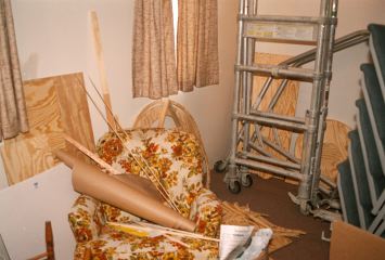
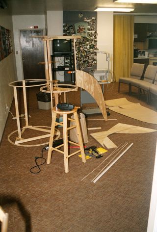
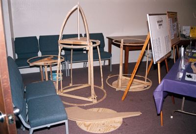
1-04: May 23. Storge room. |
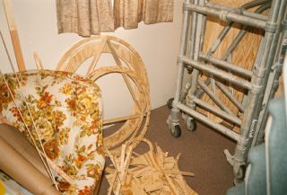
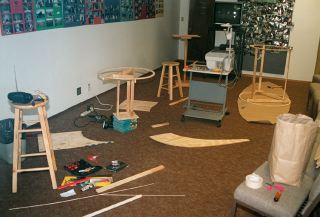
1-07: Storge room. |
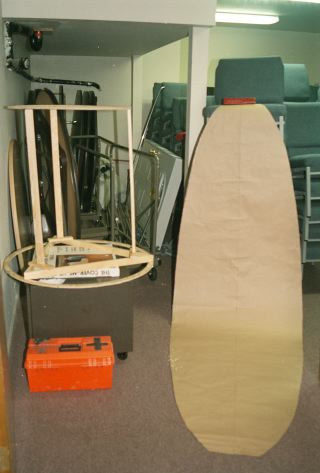
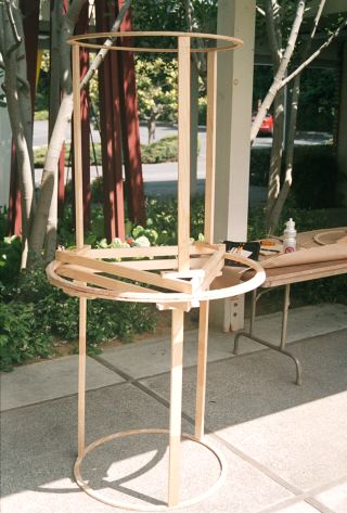
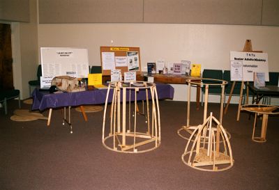
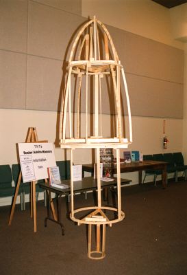
1-06: 2nd stage - temporary assembly. |
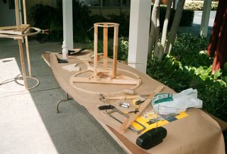
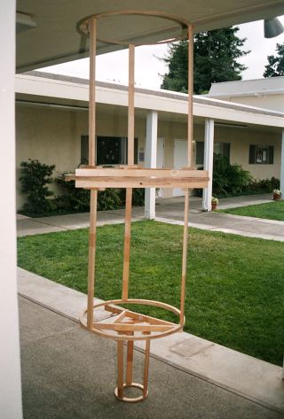
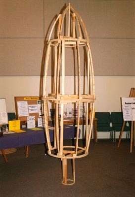
1-08: Construction of 1st and 3rd stages. |
VBS Space Mission Bible Camp
Rocket Story
If you click on an image below, you will see a larger JPEG image. The images were created from scanned negatives done by a friend of mine, Chuck Vaughn using Photoshop. The scanned image files are 1.7 mega byte TIFFs and I don't have the ftp space for them. The image numbers are the roll number - frame number. The bad news, is that AOL uses a lite version of Internet Explorer 3.0 which dithers the images. This means that the images are rendered as a low quality image ( poor resolution and color ). I suggest using an actual browser and not the built in one supplied with AOL's software. Also Internet Explorer 3.0 renders the background pattern incorrectly.
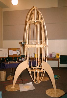
I started construction on the VBS ( Vacation Bible School ) Rocket Project on May 15, 1998 as a part of my church's VBS Space Mission Bible Camp program.
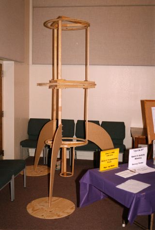
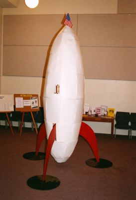
It started with a sketch I made of a cartoon rocket that I saw in several cartoons when I was a kid. From the sketch I added height and maximum width dimensions. From there I created a full size paper version of the hull, Image 1-06. The hull was used to create the dimensions of the 4 stages.
Stage 1 is the exhaust port. Stage 2 supports the fins. Stage 3 is a mirror image of stage 2 with handles for easy division of the rocket during disassembly. Stage 4 is the cockpit.
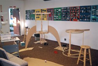
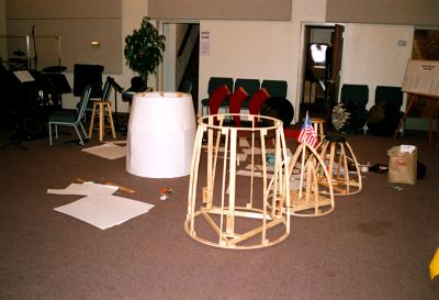
The storage room is sharing space, images 1-04, 1-07 and 2-04, with several other projects, one of them was the installation of the sound baffles in the sanctuary.
|
|
|
|
|
|
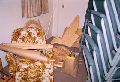
1-04: May 23. Storge room. |
1-07: Storge room. |
1-06: 2nd stage - temporary assembly. |
1-08: Construction of 1st and 3rd stages. |
Since I rent a room in a house, I have no storage space for major power tools. So the rocket was built using a drill, screw driver, hammer and a saw. These were kept in a large bag in the storage room.
I made a plum line from fishing line and a triangular weight. To each stage I used tacks on cross diagonals to create a center connection point for the plum line. The plum line is difficult to see, but is most visible in image 2-14. For final alignment the plum line hangs from the bottom of the 4th stage and hovers above the bottom of the 2nd stage.
The project had a $100 budget. I spent about $120. To meet the budget I had to minimize the amount of material used. Many people suggested, plastic, large barrels, iron, paper mashie and chicken wire, cardboard etc. Plastic and iron were to expensive let alone my not having the tools for those materials. Large barrels would not form the shape, let alone finding them. Paper mashie and chicken wire would not be strong enough, let alone survive the outside wind and rain.
My solution was wood, if I used only enough to form a frame in which to wrap some form of paper. Looking around I found weather treated white cardboard for 25 cents a sheet. I figured 30 or 40 sheets would do it. It took 39 sheets.
The wood I choose was, inexpensive plywood. The plywood was not strong enough or straight enough to handle any kind of loading, but was cheap and easy to cut into the shapes needed. The load baring wood was chosen based on price, which turned out to be fur for the internal frame and fiberboard for the fins. Fiberboard is stronger, easier to work with, straighter and can take a nail, than plywood, but was to heavy for the ribs and rings.
Since the rocket is in a cigar shape, the 2nd and 3rd stages are mirror images. The 1st and 4th stages are also mirror images except for cutting short the 1st stage to add an exhaust port.
To build the second stage ( the hardest stage first ), image 1-06, I cut a 36", 27" and 9" ring from a 4' x 4' sheet of plywood ( 5/8" thick ). To connect the 36" ring to the 27" ring, required me to create a base on the 36" ring. The base was created by cutting 3 pieces of fur and nailing them into a triangular shape. The base was nailed and screwed unto the 36" ring. The nail kept the fur from splitting when the screws were added. The screws form a much stronger and more stable connection than nails which easily pull out. At the corners of the triangular base were placed fur seats. The seats were nailed and screwed into the base. The fur support braces were then screwed into the seats. The 27" rings were then screwed into the support braces.
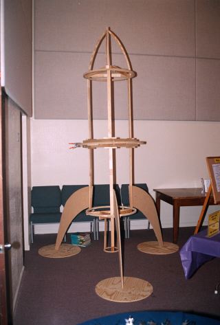
The 1st and 3rd stages were built with the same design principle, except the size difference on the 1st stage rings required an a-frame, rather than a complete triangle. The 4th stage, 2-07, is different, since there is only one ring. I placed a plywood plate on the base and screwed on a 1" dowel rod in the center. This allowed an attachment point for the ribs. The dowel rod extended about 2 inches above the tip of the rocket to allow handling the 4th stage after the skin is added. I used, three 4' x 4' sheets of plywood for all the rings. Two sheets to create 36", 27" rings and a base plate ( fin support ), and another sheet to create two 27" rings and another base plate.
After stage 2 and 3 were built, they were aligned together. 3/16" holes were drilled between the 36" rings and pined with dowel pins, during construction. This alignment and pinning process was repeated for all the stages.
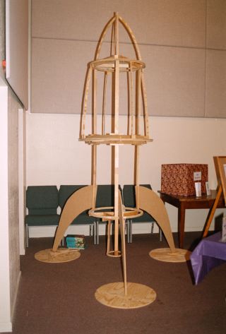
A fin template was created from the plywood scrap. The template determined were the holding pins will go and how strong and stable the fins would be. The template was used to create the 3 fins from a single 4' x 4' sheet of fiberboard. Once the fins were made, I could connect all the stages and determine the total alignment of the rocket, loading, fin stability and determine how easy it would be to assemble and disassemble it.
|
|
|
|
|
|
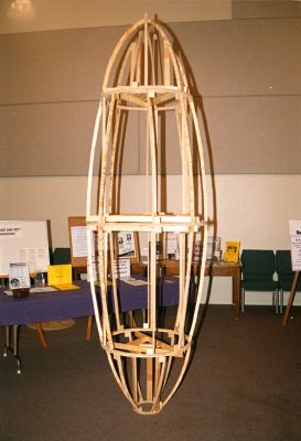
1-10: Alignment of 2nd and 3rd stages. |
1-12: Alignment of 1st, 2nd and 3rd stages. |
1-13: Fin template constructed. |
1-15: Stage 2 fin modifications. |
|
|
|
|
|
|
1-18: Final fin attachment to stage 2. |
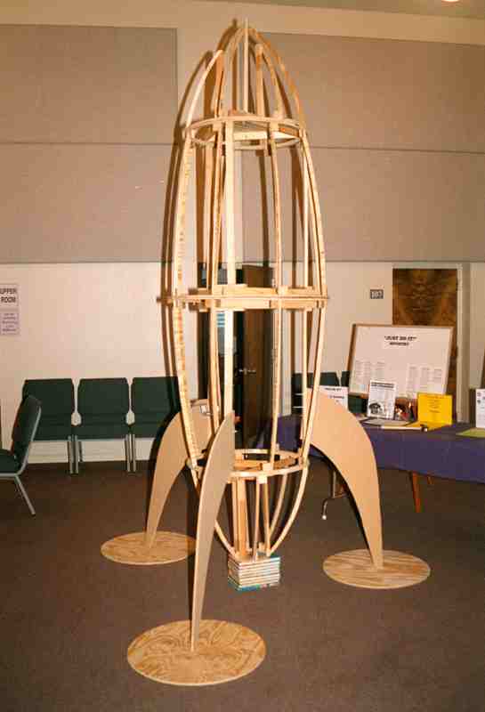
1-20: First loading of fin with all stages mounted. |
1-21: First ribs attached to stage 4. |
1-23: First ribs attached to stage 3. |
Ribbing the 3rd stage was the easiest and allowed me to determine how much ribbing would be required for the cardboard sheets available. The initial ribbing indicated I would need to double the number of ribs on each stage ( 8 ribs - 1st and 4th, 16 ribs - 2nd and 3rd ). Total number of ribs: 48. The 4th stage center rod did not have enough space for 8 ribs, so I used a short rib design, which added 3 extra support braces. The plywood turned out not to be stable enough for attachment to the rod, which required additional modification. If I had more time, I would have used fiberboard. The ribbing was a little tricky since the ribs needed to be as evenly spaced as possible, but could not be to close to the base, alignment holes, plywood layer faults or plum line pins. The ribs were attached to the rings with a support block with nails which was attached to the ring with nails. Aligning the ribs vertical was the most time consuming part, I used another plum line.
|
|
|
|
|
|
2-01: Jun 27. Second stage damged. |
2-04: Jun 28. Farris Edington cut the remaining ribs, while I repaired the second stage. Eb Bright and Tony Jorajuria supplied Farris with the power tools. |
2-06: Final ribbing of the 3rd and 4th stages begins. |
2-07: 3rd and 4th stages are ribbed. |
|
|
|
|
|
|
2-09: Reassembled the rocket after the 2nd stage was repaired. |
2-10: Final ribbing of the 2nd stage. |
2-12: Final ribbing of the 1st stage. |
2-14: First loading of the fins with all stages mounted of the repaired rocket. The plum line is visible ( silver spot at bottom of 2nd stage ). |
A single sheet of cardboard could not cover the space between ribs, so one sheet was connected to the top ring and one to the bottom ring. I used tacks to give the appearance of rivets except on the 1st stage where I used a staple gun, which is a lot easier and faster. The two dimensional form of the cardboard did not map well to the three dimensional surfaces of the rocket. This required each stage to be fitted, by cutting the attached cardboard on stress lines and gluing the cuts into a close 3D surface shape. Doubling the number of ribs would have eliminated a lot of the mismatch problems, but there wasn't enough time, money, material or space on the rings. The 2nd and 3rd stages required modification to the skin to allow for access to the fins ( 2nd stage ) and handles ( 3rd stage ).
During skinning, the fins, base plates and 1st stage were painted ( spray paint for speed ). A 1/4" hole was drilled into the dowel rod on the 4th stage to support a flag. This flag rod was not permanently attached for easy removal. The dowel pins were replaced with true alignment pins made from a fur block and 1/4" bolt. Nails attached the blocks to the rings. If you look real close you can just barely make a few of them out in image 2-16. The 1st stage pins were placed below the fin joints so that additional retaining nuts can be easily attached to hold the 1st stage in place. All the bolts were connected to their blocks with a counter sunk hole drilled to hold the retaining nuts.
To stabilize the fins from simple bumps, like the one that caused the damage ( image 2-01 ), I added clamps, that held the fins tight against the support brace.
|
|
|
|
|
|
2-16: Attachment of the 3rd stage handles. |
2-20: Jul 12. The skin is attached to the 2nd stage. A flag is added to the 4th stage. The fins, base plates and 1st stage are painted. |
2-22: The rocket is reassembled with the fins fitted to the skinned 2nd stage. |
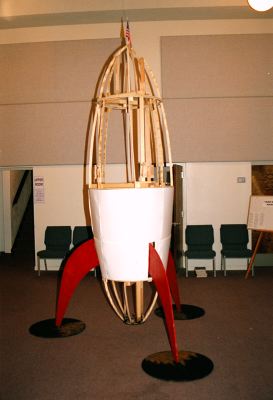
2-23: Jul 13. The 3rd stage is skinned. |
It takes about 15 mins to disassemble the rocket, move it to another location and then reassemble it. I didn't have enough time to really complete the rocket. Things left to do were: add the portal and puppet astronaut to the 4th stage, add the access panels to cover the fin and handle openings, paint the flag rod, add the knob at the top of the flag rod, the pluming hole for the smoke effect, the vertical support rod ( attached to the 3rd stage handles ) to stabilize the rocket in the wind when outside and replace the metal clamps with permanent wooden ones on the fins.
After building this rocket, experience dictates a change in the design. First I would build the frame rectangular rather than triangular. The rings would be made of segments, attached to the frame at key points. This would cut down a lot on the amount of material needed and make attachment of the cardboard much easier. I would build six stages to decrease the loading on the support braces. I would use the staple gun to attach the skin and paint the rivet heads onto the skin. I would start a lot sooner on the project.
|
|
|
|
|
|
3-00: Jul 14. The 3rd stage is skinned and fitted. The 4th stage skin is almost completed. |
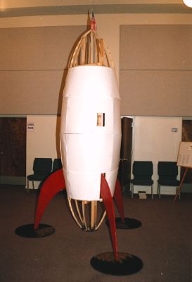
3-23: Jul 15. All stages, skin fitted. |
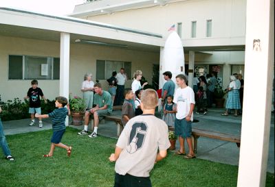
4-01: Jul 17. The rocket is moved outside for Friday's closing ceremonies. |
VBS Space Mission Bible Camp. |
Last updated: Mar 4, 2011